Bend
## Copyright © EDF 2002 - 2026
## ThermoSysPro Version 4.2
This component model is documented in Sect. 13.6 of the ThermoSysPro book.
# Bend
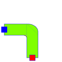
The bend models the singular pressure loss of a fluid circulating inside a bend pipe. For water/steam, the flow regime can be single-phase or homogeneous two-phase flow.
Following assumptions are made:
- The flow inside pressure losses is adiabatic. Non-adiabatic pipes must be
modeled by connecting pressure losses to volumes.
- The specific enthalpy inside the components is equal to the specific enthalpy at the inlet.
- The properties of the fluid are computed for the average pressure..
- Inertia due to momentum inside pipes is neglected.
The friction pressure loss coefficient is calculated using the geometry of the bend. The bend thus completes the [singular pressure loss component](modelica://ThermoSysPro.WaterSteam.PressureLosses.SingularPressureLoss), in which the pressure loss coefficient is a single parameter.
## Modelica component model
The equations mentioned below are implemented in the component *Bend*, located in the *WaterSteam.PressureLosses* sub-library.
This component has 2 connectors:
- C1: fluid inlet,
- C2: fluid outlet.

## Nomenclature
| Symbol| Description| Unit| Definition| Modelica name |
| :------------------ | :------------------------------------------------ | :------------------------------- | :-------------------------------------------------------------- | :----------- |
| \\(A\_{1}\\)| Factor for the singular pressure loss coefficient | \\(-\\)|| yA1 |
| \\(B\_{1}\\)| Factor for the singular pressure loss coefficient | \\(-\\)|| yB1 |
| \\(C\_{1}\\)| Factor for the singular pressure loss coefficient | \\(-\\)|| yC1 |
| \\(D\\)| Internal diameter of the bend| \\(\mathrm{m}\\)|| D |
| \\(h\\)| Fluid specific enthalpy at the inlet| \\(\mathrm{J} / \mathrm{kg}\\)|| h |
| \\(K\_{\varepsilon}\\) | Roughness factor| \\(-\\)|| kdelta |
| \\(\dot{m}\\)| Fluid mass flow rate| \\(\mathrm{kg} / \mathrm{s}\\)|| Q |
| \\(P\_{\mathrm{i}}\\)| Fluid pressure at the inlet| \\(\mathrm{Pa}\\)|| C1.P |
| \\(P\_{\mathrm{o}}\\)| Fluid pressure at the outlet| \\(\mathrm{Pa}\\)|| C2.P |
| \\(R\\)| Bend radius| \\(\mathrm{m}\\)|| R0 |
| \\(Re\\)| Reynolds number| \\(-\\)| \\(\frac{4 \cdot \lvert \dot{m} \rvert}{\pi \cdot D \cdot \mu}\\) | Re |
| \\(Re\_{\lim }\\)| limiting Reynolds number| \\(-\\)|| Relim |
| \\(\delta\\)| Bend angle| \\(\circ\\)|| delta |
| \\(\Delta P\\)| Pressure loss between the inlet and the outlet| \\(\mathrm{Pa}\\)| \\(P\_{\mathrm{i}}-P\_{\mathrm{o}}\\)| deltaP |
| \\(\varepsilon\\)| Pipe roughness| \\(\mathrm{m}\\)|| rugosrel |
| \\(\zeta\\)| Hydraulic pressure loss coefficient| \\(-\\)|| khi |
| \\(\zeta\_{m}\\)| singular pressure loss coefficient| \\(-\\)|| khim |
| \\(\zeta\_{f}\\)| Friction pressure loss coefficient| \\(-\\)|| khif |
| \\(\lambda\\)| Friction pressure loss coefficient| \\(-\\)|| lambda |
| \\(\mu\\)| Fluid dynamic viscosity| \\(\mathrm{Pa} \mathrm{s}\\)|| mu |
| \\(\rho\\)| Fluid density| \\(\mathrm{kg} / \mathrm{m}^{3}\\) || rho |
## Governing equations
### Static momentum balance equation
- Validity domain:
\\(\forall \dot{m}\\)
- Mathematical formulation:
$$\Delta P=8 \cdot \zeta \cdot \frac{\dot{m} \cdot \lvert \dot{m} \rvert}{\pi^{2} \cdot D^{4} \cdot \rho}$$
- Comments:
### Hydraulic pressure loss coefficient
- Validity domain:
\\(\forall \dot{m}\\) with \\(Re>Re\_{\lim }\\)
- Mathematical formulation:
$$\zeta=K\_{\varepsilon} \cdot \zeta\_{m}+\zeta\_{f}$$
$$ K_{\varepsilon} = \left\{ \begin{array}{l} 2 \; \text{if} \; \varepsilon \geq 10^{-3} \\ 1 + 10^3 \cdot \varepsilon \; \text{if} \; \varepsilon<10^{-3} \; \text{and} \; \frac{R}{D}<1.5 \\ 1 + 10^6 \cdot \varepsilon^2 \; \text{if} \; \varepsilon<10^{-3} \; \text{and} \; \frac{R}{D} \geq 1.5 \end{array} \right.$$
$$\zeta\_{f}=0.0175 \cdot \lambda \cdot \frac{R}{D} \cdot \delta$$
$$\zeta\_{m}=A\_{1} \cdot B\_{1} \cdot C\_{1}$$
- Comments:
The limiting Reynolds number is given by:
$$ Re_{\lim } = \left\{ \begin{array}{l} 2 \times 10^{5} \; \text{if} \; \varepsilon<5 \times 10^{-5} \\ \max \left(\frac{560}{\varepsilon}, 2 \times 10^{5}\right) \; \text{if} \; \varepsilon \geq 5 \times 10^{-5} \end{array} \right.$$
## References
El Hefni, Baligh and Bouskela, Daniel (2019). [Modeling and Simulation of Thermal Power Plants with ThermoSysPro](https://link.springer.com/book/10.1007/978-3-030-05105-1), sect. 13.6. Springer Nature Switzerland AG.
Author Daniel Bouskela
Generated at 2026-08-05T20:24:29Z by OpenModelicaOpenModelica 1.27.0 using
GenerateDoc.mos
 .ThermoSysPro.WaterSteam.PressureLosses.Bend